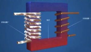
A transformer is just a pair of inductors that are magnetically coupled to achieve electromagnetic induction between them. With the help of transformers, AC voltage can gradually increase or decrease at a lower cost without any trouble. Raising or lowering DC voltage requires complex and expensive circuits. This is why even if most electronic devices operate using DC, AC is used to distribute power. Electronic devices convert AC power into DC to perform their functions.
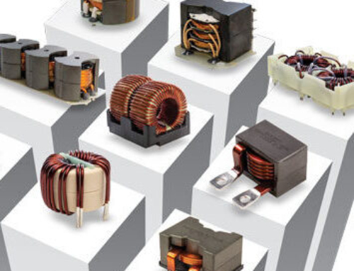
Transformers come in various shapes, sizes, and constructions. Transformers can be classified based on core material, geometric shape and structure, voltage level, and purpose.
Core structure classification: laminated core, Ferrite core, iron powder core, empty core
Classification of external structure: solenoid core, annular magnetic core, pot core
Classification of voltage level: step-up, step-down, isolation
Usage classification: power transformer, Pressure regulator, reactor, mutual inductor, special transformer

1〠Transformer core
When manufacturing any transformer, manufacturers attempt to achieve maximum magnetic coupling between two inductors. By using ferromagnetic materials or iron powder as magnetic cores, magnetic coupling can be increased many times. Compared to hollow transformers, a pair of inductors wound around a ferromagnetic core has a better coupling coefficient. However, the use of ferromagnetic cores has its own limitations. Ferromagnetic cores have some energy losses due to hysteresis and eddy currents, and are also limited by their current carrying capacity. In addition to these limitations, the selection of core materials also limits the frequency range of transformers. According to the type of iron core used, transformers are classified as follows
Stacked iron transformers: These transformers use silicon steel as the core material. Silicon steel is also known as transformer iron or simply referred to as iron. Silicon steel is laminated into layers to avoid losses caused by eddy currents and hysteresis. Eddy current is a circular current flowing in magnetic materials during magnetization. Eddy current causes the magnetic core to lose energy in the form of heat. Hysteresis is the tendency of a magnetic core to accept fluctuating magnetic flux. Due to hysteresis and eddy current losses, these transformers are only suitable for 60 Hz frequencies and other low frequencies within the audio range. When the frequency increases to over a few thousand hertz, the internal loss of the iron core will increase beyond the feasible limit.
Ferrite core: Ferrite core has high permeability and requires less coil turns. However, at frequencies above a few megahertz, this type of magnetic core begins to exhibit significant energy loss due to eddy currents and hysteresis. That’s why these transformers are suitable for audio frequencies up to a few megahertz.
Iron powder core: Compared to ferrite cores, iron powder also has higher magnetic permeability and lower losses, which are attributed to hysteresis and eddy currents. As the frequency increases, the demand for high magnetic permeability decreases. Transformers with iron cores are suitable for very high frequencies up to 100 MHz. Since it is not necessary to achieve high permeability at extremely high frequencies higher than 100 MHz, air core transformers are more suitable because of their higher energy efficiency.
Air core transformer: in the air core transformer, the primary coil and secondary coil are wound on Diamagnetism materials. The magnetic coupling in this type of transformer occurs through air. In such a transformer, not only is the inductance of both coils low, but also the mutual inductance is very low, so the magnetic coupling between the coils is very small. These transformers do not lose energy due to hysteresis or eddy currents, and can also regulate large currents. This type of transformer is suitable for high-voltage applications where energy efficiency is the primary concern, such as distribution transformers. These are also applicable to ultra-high RF applications above 100 MHz. At high RF, the required inductance value is very low, which can be easily achieved through hollow inductors.
2〠The shape and construction of transformers
Transformers can also be classified based on their shape and geometric shape. The shape of a transformer depends on the type of inductor used in its construction and the shape of its iron core. Any transformer is essentially a pair of inductors wound around the same magnetic core. The classification is as follows:
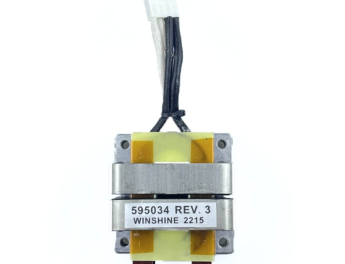
Utility transformer: Utility transformer is a power transformer that uses laminated iron sheet as the core material. These iron core transformers have various core shapes, such as E, L, U, I, etc., and are bulky and bulky. The most commonly used core shape among these transformers is the E core or EI core, as the shape of the laminated core is the letter “E” and a rod is placed at the open end of “E” to complete the structure. The coil is wound onto the core using either the shell method or the core method. In the shell method, both coils are wrapped at the top of each other on the middle strip of ‘E’. This ensures maximum magnetic coupling between coils, but at the cost of high coil to coil capacitance. The shell method also limits the current carrying capacity of transformers. In the magnetic core method, one coil is wound around the top strip of “E” and the other coil is wound around the bottom. The magnetic coupling between coils occurs only due to the magnetic flux passing through the iron core. The magnetic core method greatly reduces the capacitance from coil to coil and makes it possible to handle high voltages. Utility transformers with EI cores and shell or core windings are most commonly used as 60 Hz transformers and other audio transformers.
Electromagnetic coil transformer: Electromagnetic coil transformer is usually used as a loop antenna for RF circuits. These transformers have primary and secondary windings on cylindrical cores (ferrite or iron powder). The coils are wound or separated from each other. In such a transformer, the primary winding captures the radio signal, while the secondary winding provides impedance matching for the first amplifier stage of the radio circuit. Such transformers are already very common in portable radio communication equipment.
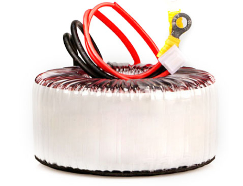
Ring iron core transformer: The primary and secondary windings of the ring iron core transformer are wrapped around the ring iron core, and the coils may be wrapped around each other or separately. Circular magnetic cores are a better alternative to solenoid magnetic cores in RF circuits. They contain magnetic flux within the iron core, so as long as the coil is insulated, these transformers can be installed directly without any other shielding. In addition to the absence of electromagnetic interference, each coil of the circular core also provides higher inductance. Due to the fact that the magnetic flux is still contained within the iron core, the circular iron core transformer has better magnetic coupling between the coils.
Tank core transformer: The main and secondary windings of a tank core transformer are stacked or adjacent to each other. The pot core can provide the highest inductance and has a clear advantage of self shielding. One of the main drawbacks of pot core transformers is the capacitance from coil to coil. Due to the abnormally high capacitance between the coils and the inductance between the two coils, the pot shaped iron core transformer is only suitable for low frequencies. At high frequencies, the required inductance value is very low, and the capacitance reactance must be basically reduced.
3〠Transformer voltage level transformer
The most common application is to regulate AC voltage. Transformers can increase, decrease, or maintain a complete AC voltage level. This is the simplest but most important transformer classification.
Step-up transformer: In a step-up transformer, the number of turns of the secondary coil is higher than that of the primary coil. When the ratio of turns between the primary and secondary is less than 1, the voltage applied to the primary will rise to the higher voltage in the secondary. Therefore, this comes at the cost of lower current levels on the secondary winding. Step-up transformers are used for stabilizers and inverters, where lower AC voltages need to be converted to higher voltages. They are also used in the power grid to increase the AC voltage level before distribution.
Step-down transformer: In a step-down transformer, the number of turns in the primary coil is higher than that in the secondary coil. When the ratio of turns between the primary and secondary windings is greater than 1, the secondary voltage will be lower than the primary voltage. Step-down transformers are typically used in electronic applications. Electronic circuits typically require 5V, 6V, 9V, 12V, 18V, or 24V operation. A step-down transformer is usually used in a power circuit, which reduces the voltage of a 120V or 240V AC power supply to the desired low voltage level before a rectifier. In power distribution, a step-down transformer is used to reduce high voltage and supply power to both poles. This ensures the energy efficiency and cost-effectiveness of distribution.
Isolation transformer: The primary and secondary turns of the isolation transformer are the same. Due to the ratio of turns between the primary and secondary windings being exactly 1, the voltage levels on both windings remain the same. These transformers are used to provide electrical isolation between electronic circuits or eliminate noise transmission from one circuit to another. Isolation transformers need to have high inductance coupling and minimum capacitance coupling. This is why these transformers are designed to have the minimum number of turns on independent coils wound around high magnetic and self shielding iron cores.
Isolation transformers are also used to connect balanced and unbalanced circuits. A balanced circuit refers to a circuit that can be connected in any way across ports. Unbalanced circuits refer to circuits that need to be connected across ports in a specific way. Balanced and unbalanced loads can be connected through isolation transformers by grounding the center tap of the balance center. If the balanced load and the unbalanced load have the same impedance, the turn ratio of the isolation transformer should be 1. If the balanced load and the unbalanced load have different impedance ratios, the turn ratio should match the square of the impedance ratio.


